Discover CAM Motion Profile Optimizations
CAM Motion Profile Optimization
In 5 steps towards optimized motion profiles using the eMotionizer
- Motion trajectories are optimized by employing a simplified virtual twin of the actual machine. Therefore, at first, it is essential to determine the model-parameter values that allow us to predict the drive line behavior as realistically as possible. These model parameters, often position-dependent, include mechanical concepts such as inertia, gravity, or friction and are determined from the viewpoint of the driving motor. For straightforward mechanisms, one can calculate the model properties by hand. However, as demonstrated in the instruction video, existing CAD models can be combined with motion simulations to extract these properties accurately (except for friction).
✅ Complete the provided CSV template to upload the required mechanical system properties to the eMotionizer website.
✅ The required properties should be provided as a function of the position, even if the properties are not position-dependent.
✅ If no friction information is available, we advise to set the friction value to zero.
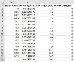
Example 1: Drive line mechanical system properties with position-dependent inertia and load torque values, and unknown friction. These values can be employed to optimize between 0 and 1 rad.
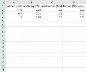
Example 2: Drive line mechanical system properties with fixed inertia and load torque values. A friction estimation is provided. These values can be employed to optimize between 0 and 1 rad.
- Upload your drive line system properties to the eMotionizer website using the CSV template and verify the result. If the values are displayed correctly, you are good to go.
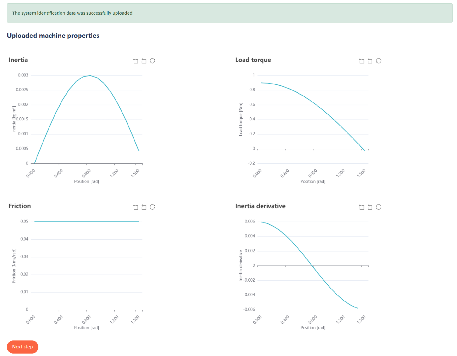
The website automatically shows the uploaded system properties. If they are displayed correctly, you are good to go.
- Choose an optimization objective (e.g., minimal peak torque) and complete the required optimization constraint fields (e.g., the motions start and end point) marked with a tick border. Moreover, if desired, using fields with thin borders can add additional constraints. Nevertheless, the more additional constraints applied, the higher the chance an optimization would fail without a result. To guide you optimally, additional instructions marked by ‘‘ are available.
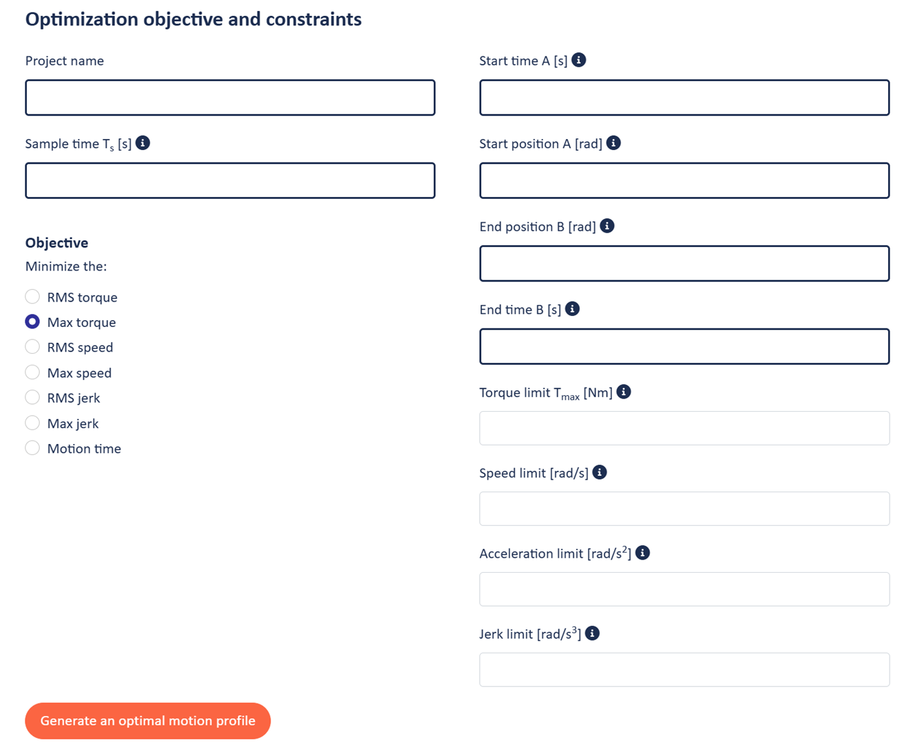
- Run the eMotionizer and optimize! Depending on your plan, you pay per period or simulation using credits.
- Evaluate the optimization online and download the result in a handy .csv format, whereupon it can be used to implement the trajectory on your favorite motion platform (e.g., Beckhoff, Siemens, …). As a motion profile optimization reference, a polynomial of a 5th order is used by default. Also, the optimized profile has a polynomial basis.
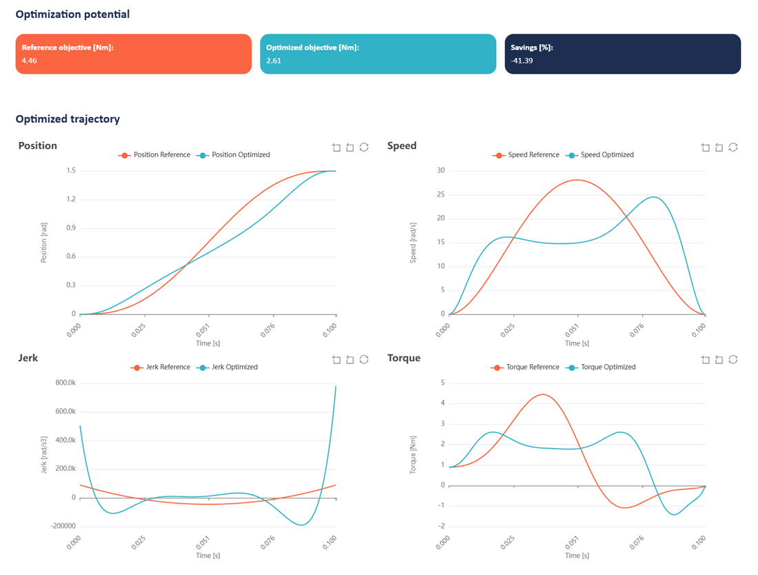
Website: The website provides a graphical overview of the optimization result. As a motion profile optimization reference, a polynomial of a 5th order is used by default.
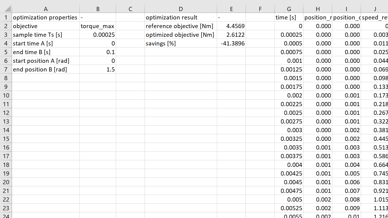
CSV: The optimization result can be downloaded in a handy CSV file format. The file includes information such as the optimization objective and constraints, the profit obtained, and the actual position, speed, torque, and trajectories. The latter can directly be used to implement the motion profile on the drive of your choice.
Motor Drive Control Loop Parameter Optimization
Enhance your motor drive speed control loop parameters fast and easy in 5 steps
- Many machines, systems, or drive lines consist of interconnected mechanical parts, and in the case of the eMotionizer, driven by an electrical motor. To optimize the parameters regulating the speed control loop, the eMotionizer uses the frequency spectrum signature of the drive line. An easy system identification experiment executed on the drive is necessary to obtain this signature. Since the experiment principle is easy, it is executable using almost any drive platform. The video below gives more detailed information on how to perform this experiment.
✅ Upload the result of the necessary identification experiment by completing the CSV template.
✅ Adjust the experiment parameters, e.g., the excitation amplitude or the sample time, to maximize the identification result.
✅ If the inertia is not constant, the experiment should be executed near the inertia peak value.
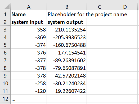
Template CSV file to be completed with experiment data and uploaded to the website. The video explains what the template refers to as ‘input’ and ‘output’.
- Upload your system identification experiment data using the template. The website will notify you if the data is received well. Supplementary, once the data is uploaded, fill out the boxes in the identification experiment menu and choose a method to optimize the control loop parameters. Run the eMotionizer a first time to generate a frequency domain representation of your drive line.
✅ The in-and-output scaling values help you relate the units of your experiment data with the controller units. For two motion platforms, the scaling values are provided as examples. The video above provides a more detailed explanation on how to determine scaling values.
✅ Two different optimization principles are available:
-
- The Anti Resonance method is advisable if quick tuning and a stable balance between controller reaction time and stability are preferable. In 90% of the cases, we recommend this tuning method.
- If performance is why you use the eMotionizer, the Phase Margin method is the way to go. This method uses an additional notch filter, requires extra effort, and is more complex, but outperforms the anti-resonance method.
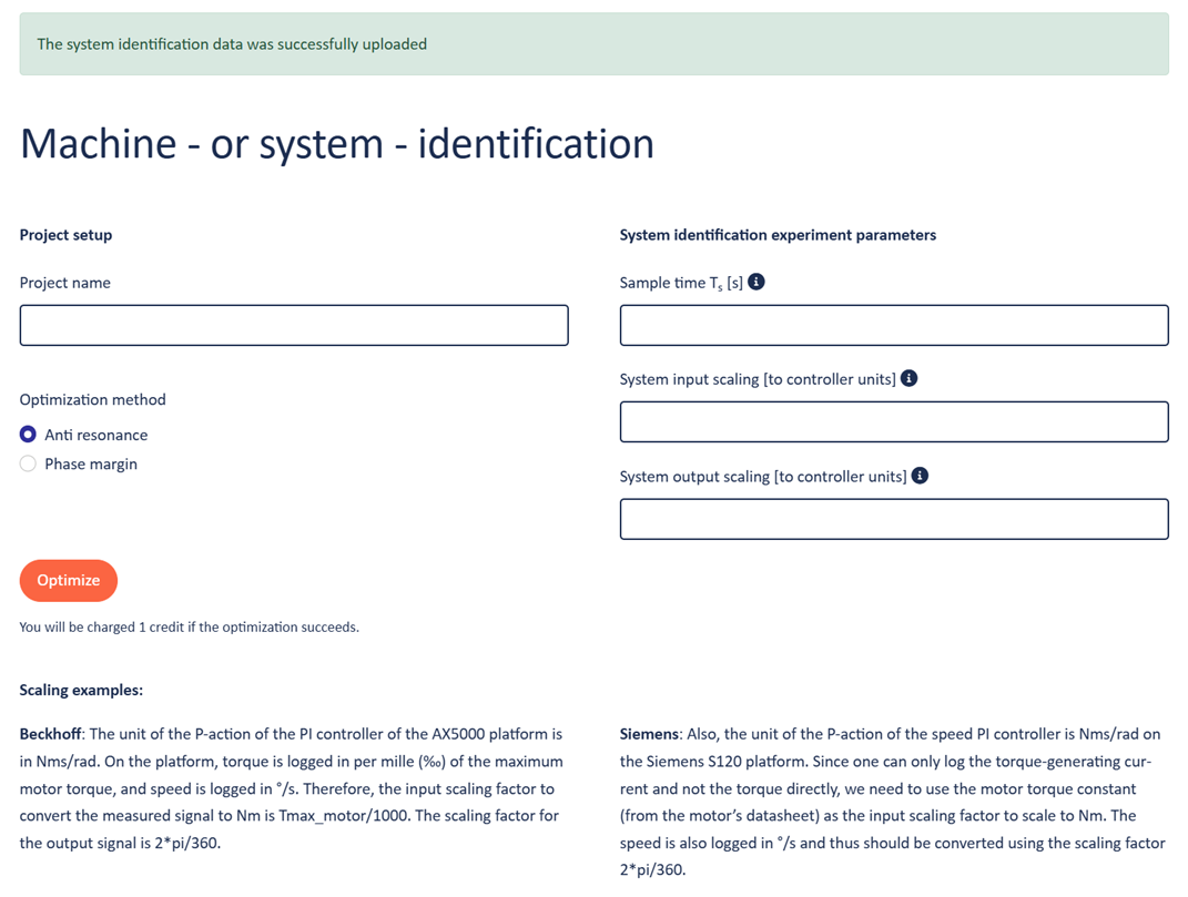
Scaling parameters should be determined to complete the system identification experiment and determine the frequency spectrum signature, among others. Moreover, one should choose between the Anti Resonance or Phase Margin to optimize the values of the PI-speed controller.
- After running the eMotionizer and before building upon the determined frequency spectrum signature, validating this signature is very important for the trustworthiness of the eventual control loop parameters. The results can be validated by evaluating the coherence, which should be close to 1. Moreover, one can further validate the system by adding drive line asymptotes free of charge. Watch the above video for more information on this topic.
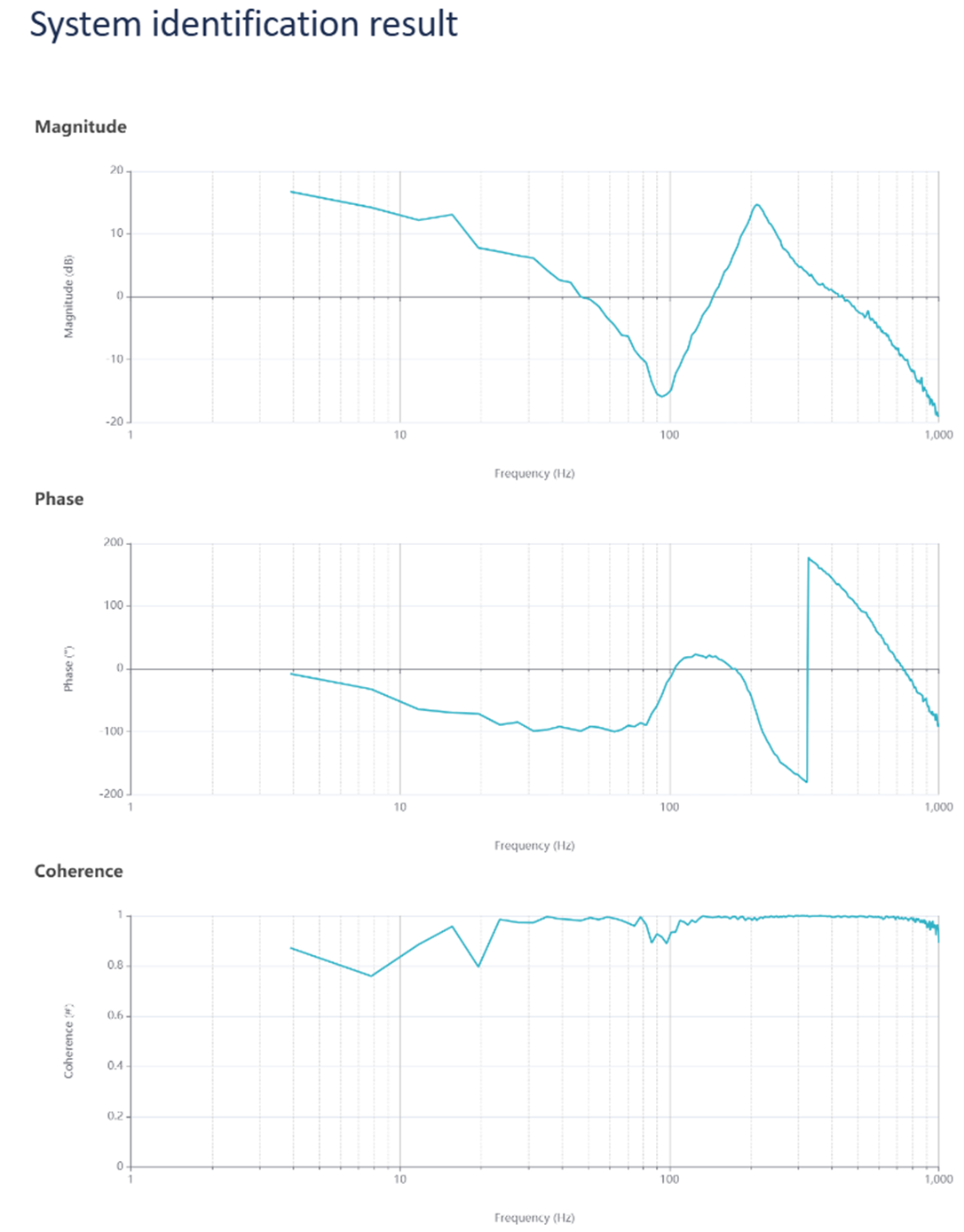
Determined frequency spectrum signature employing the eMotionizer. Subplot 3 shows the coherence, which is close to 1 as desired.
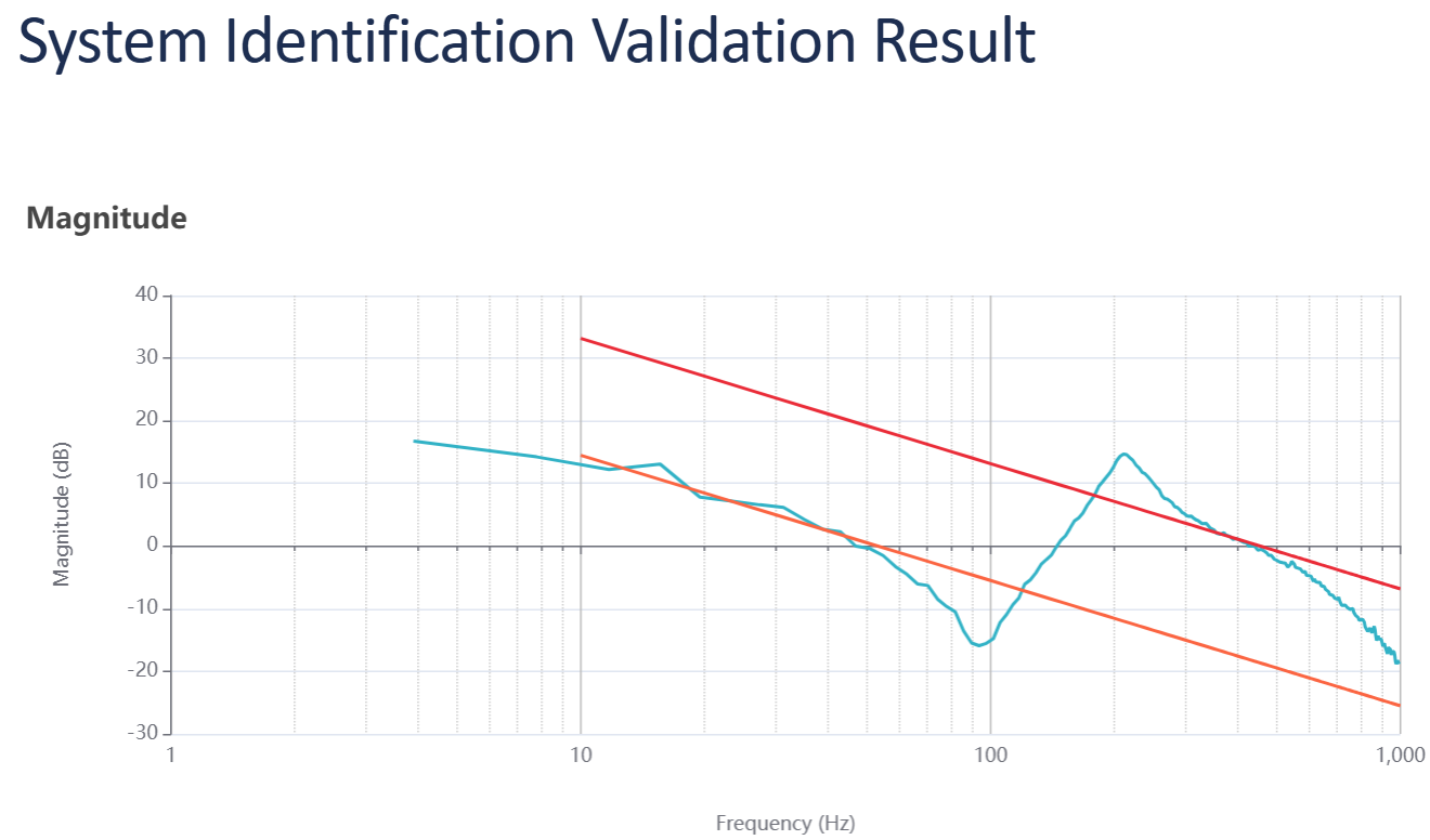
Frequency spectrum signature validation using inertia asymptote lines. As desired, both lines ‘touch’ the experiment result.
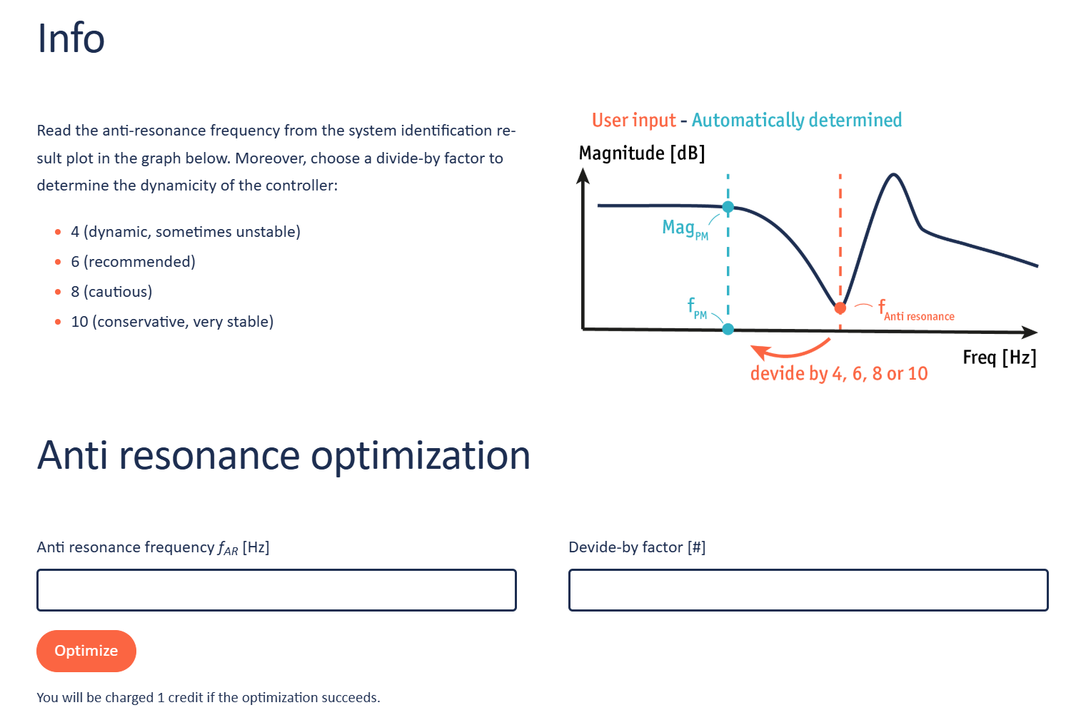
- Read the anti-resonance frequency from the system identification result graph as illustrated in the demonstration figure, choose the dynamicity of the controller, and run the eMotionizer a second time to obtain optimal speed P & I controller values. In the case of the phase margin method, the workflow is very similar.
- Evaluate the optimization online and download the result in a handy .csv format. The settings for the controller, and in the case of the phase margin method also the settings of the notch filter, can be copied directly from the website. The CVS can be downloaded to store or share the results.
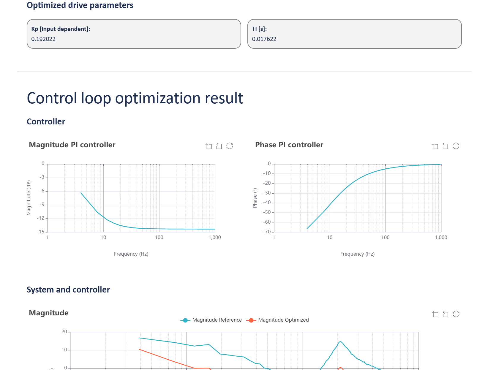
Website: The website shows the optimized control loop settings. The open-loop controller and the combination of the controller and the identified system are graphically displayed. When optimizing utilizing the phase margin method, the website will first show the notch filter and eventually also the control loop parameters.
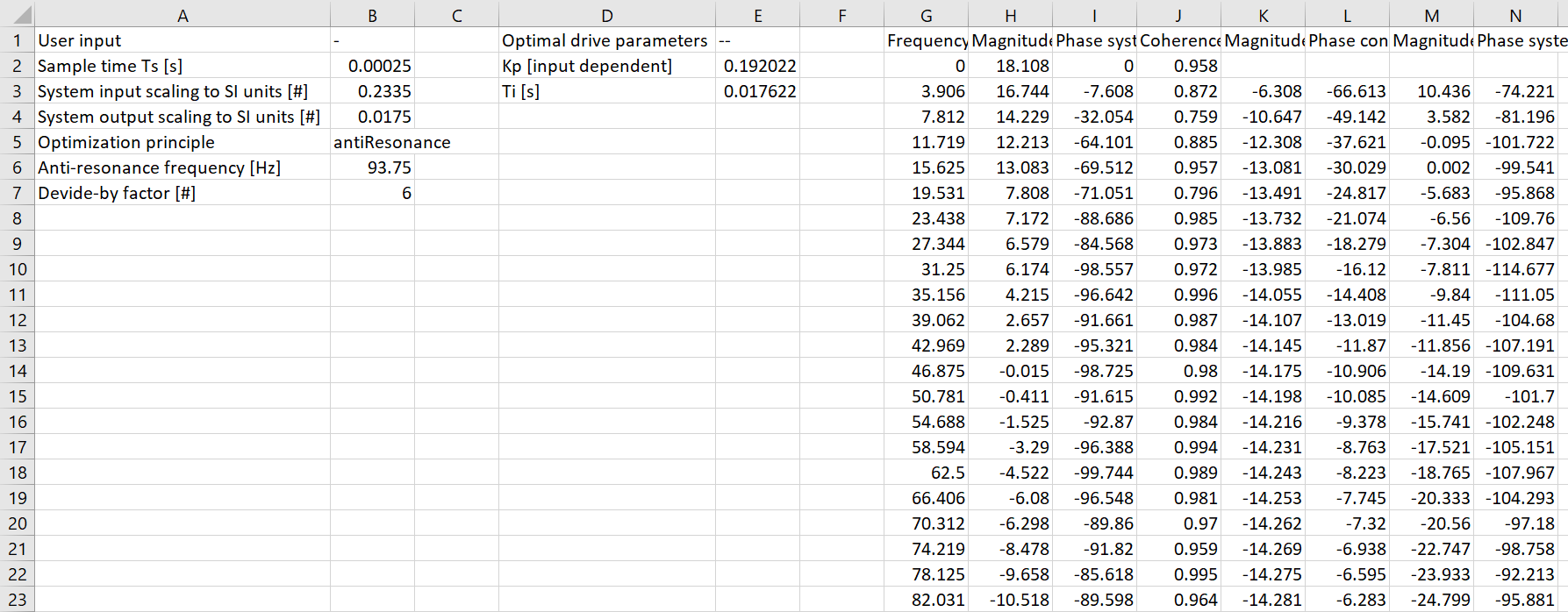
CSV: The result can be downloaded in a handy CSV file format for storage purposes. The file includes all optimized drive parameters of both the controller and – in the case of the phase margin method – the notch filter. Moreover, the CSV condenses all user input employed to optimize, and all obtained magnitudes, phases, and coherences.

